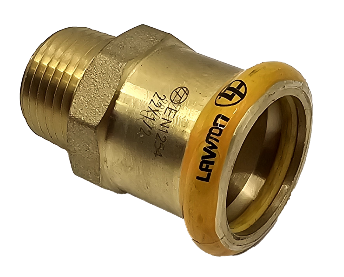
MALE BRASS ADAPTOR PRESS GAS
Gas Press Fittings
| Part | Description | Size 1 | Size 2 | Bag | Box |
|---|---|---|---|---|---|
| PFGCPMI0151/2 | 15MM X 1/2" MALE ADAPTOR BRASS GAS | 15MM | 1/2" | 10 | 250 |
| PFGCPMI0153/4 | 15MM X 3/4" MALE ADAPTOR BRASS GAS | 15MM | 3/4" | 10 | 200 |
| PFGCPMI0221/2 | 22MM X 1/2" MALE ADAPTOR BRASS GAS | 22MM | 1/2" | 10 | 200 |
| PFGCPMI0223/4 | 22MM X 3/4" MALE ADAPTOR BRASS GAS | 22MM | 3/4" | 10 | 200 |
| PFGCPMI0281 | 28MM X 1" MALE ADAPTOR BRASS GAS | 28MM | 1" | 10 | 80 |
| PFGCPMI0283/4 | 28MM X 3/4" MALE ADAPTOR BRASS GAS | 28MM | 3/4" | 10 | 120 |
| PFGCPMI03511/4 | 35MM X 1.1/4" MALE ADAPTOR BRASS GAS | 35MM | 1 1/4" | 1 | 60 |
| PFGCPMI04211/2 | 42MM X 1.1/2" MALE ADAPTOR BRASS GAS | 42MM | 1 1/2" | 1 | 40 |
| PFGCPMI0542 | 54MM X 2" MALE ADAPTOR BRASS GAS | 54MM | 2" | 1 | 20 |
Press Gas Male Adaptor Brass
The Lawton Press Gas Male Adaptor Brass is designed to provide a secure connection between copper gas press-fit pipework and male threaded components. Manufactured with a durable brass threaded section, this fitting offers a reliable solution for connecting gas pipework systems efficiently.
The advanced press-fit design enables a fast, heat-free installation without the need for soldering, welding or hot works. This helps reduce installation time, minimise labour requirements and provides a secure, leak-tight connection.
Designed for use with compatible press tools, the fitting features a yellow sealing ring and yellow identification marking to clearly indicate its suitability for gas applications. Backed by Lawton’s 75-Year Warranty, it ensures dependable long-term performance.
Key Features
- Connects copper gas pipework to male threaded components
- Brass threaded connection for durability
- Fast and efficient press-fit installation
- No soldering, welding or hot works required
- Secure, leak-tight connection
- Yellow HNBR sealing ring for gas applications
- Lawton’s yellow identification marking for easy recognition
- Suitable for copper tube manufactured to EN1057
- Available in sizes from 15mm to 54mm
- Backed by a 75-Year Warranty
Technical Data
Product Overview
Lawton Gas Press Fittings provide a safe, heat-free jointing solution for Family 2 and Family 3 fuel gas systems and compressed air applications. Available in sizes from 15mm to 54mm, the range features an M-profile press connection with a yellow HNBR seal and is manufactured in accordance with EN 1254-7.
Applications
- Family 2 Fuel Gas Systems
- Family 3 Fuel Gas Systems
- Compressed Air Systems
Market Sectors
- Domestic
- Commercial
Product Specifications
|
Property |
Specification |
|
Size Range |
15mm – 54mm |
|
Materials |
CW024A Copper and CW602N DZR Brass |
|
Seal Material |
Yellow HNBR O-Ring |
|
Press Configuration |
M-Profile |
|
Maximum Fuel Gas Pressure |
5 bar (Outdoors), 1 bar (Indoors) |
|
Maximum Negative Pressure |
>0.2 bar |
|
Maximum Compressed Air Pressure |
10 bar (5°C to 35°C) |
|
Ambient Temperature Range |
-20°C to +70°C |
|
Product Marking |
Size, LTC Logo, EN 1254 |
|
Electrical Continuity |
Yes |
|
Thread Specification (Male) |
ISO 7 / EN 10226-1 |
|
Thread Specification (Female) |
BS EN ISO 228 |
|
Standard |
EN 1254-7 |
|
Warranty |
75 Years* |
*Subject to standard Terms & Conditions. Please refer to our website for full details.
Standards & Compliance
|
Category |
Standard |
|
Gas Press Fittings |
EN 1254-7 |
|
Male Threads |
ISO 7 / EN 10226-1 |
|
Female Threads |
BS EN ISO 228 |
Operating Performance
|
Property |
Value |
|
Maximum Fuel Gas Pressure (Indoor) |
1 bar |
|
Maximum Fuel Gas Pressure (Outdoor) |
5 bar |
|
Maximum Compressed Air Pressure |
10 bar |
|
Ambient Temperature Range |
-20°C to +70°C |
|
Electrical Continuity |
Yes |
Copper Tube Compatibility
Compatible with copper tube manufactured to BS EN 1057.
Material Conditions
- R250 – Half-hard, bendable
- R290 – Hard, unbendable
|
Outside Diameter |
0.7mm Wall |
0.9mm Wall |
1.0mm Wall |
1.2mm Wall |
1.5mm Wall |
2.0mm Wall |
2.5mm Wall |
|
15mm |
R250 |
— |
R250 / R290 |
— |
— |
— |
— |
|
22mm |
— |
R250 |
— |
R250 / R290 |
— |
— |
— |
|
28mm |
— |
R250 |
— |
R250 / R290 |
— |
— |
— |
|
35mm |
— |
— |
R290 |
R250 / R290 |
R290 |
— |
— |
|
42mm |
— |
— |
R290 |
R250 / R290 |
R290 |
— |
— |
|
54mm |
— |
— |
— |
— |
R290 |
R290 |
R290 |
Recommended Minimum Fitting Clearance
To allow for tube deformation during pressing, the following minimum distances should be maintained between adjacent fittings.
|
Tube Size |
Minimum Clearance F (mm) |
|
15mm |
13 |
|
22mm |
13 |
|
28mm |
13 |
|
35mm |
13 |
|
42mm |
16 |
|
54mm |
20 |
Approved Press Tools
Lawton Gas Press Fittings are approved for use with M-profile press systems from:
- Novopress
- Geberit
- Rothenberger
- REMS
Important Installation Note
Matching press tools, adaptors, jaws and slings from the same manufacturer must always be used during installation.
Tool Compatibility
|
Manufacturer |
Model |
Diameter Range |
|
Novopress |
ACO103 |
15mm – 28mm |
|
Novopress |
ACO203 |
15mm – 54mm |
|
Novopress |
ACO203XL |
15mm – 54mm |
|
Geberit |
ACO103plus |
15mm – 35mm |
|
Geberit |
ACO203plus |
15mm – 54mm |
|
Geberit |
ACO203XLplus |
15mm – 54mm |
|
Rothenberger |
Compact TT |
15mm – 28mm |
|
Rothenberger |
Compact 3 |
15mm – 35mm |
|
Rothenberger |
Romax 4000 |
15mm – 54mm |
|
REMS |
Mini-Press |
15mm – 28mm |
|
REMS |
Akku-Press |
15mm – 28mm |
Material Compatibility
Dissimilar Metals
Installations containing mixed metals should generally be avoided, as galvanic corrosion may occur where different metals are connected directly together.
Where mixed-metal systems are unavoidable:
- Follow the Gas Safety (Installation and Use) Regulations 1998.
- Apply recognised engineering best practice.
- Consider suitable isolation measures where required.
1. PREPARATION:
• Ensure the O-ring is present & is seated correctly (not loose in the fitting).
• Cut the tube square.
2. TUBE PREPARATION:
• Check the tube ends are not damaged.
• De-burr the end of the tube.
• Ensure no sharp edges or swarf are present.
3. INSERTION AND DEPTH MARKING:
• Insert the tube into the fitting using a “twisting motion”.
• Using a permanent pen place a mark on the tube to indicate that the fitting is fully engaged.
• When all tubes are inserted double check the “depth marks” are in the correct position.
4. PRESS THE JOINT:
• Ensure the correct tool and jaws are selected.
• Place the jaw around the “bead” of the fitting.
• When correctly located press the trigger button to commence the pressing process.
• The tool will automatically stop when this is complete.
• Remove the pressed assembly from the jaw.