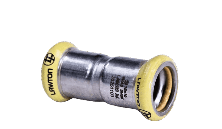
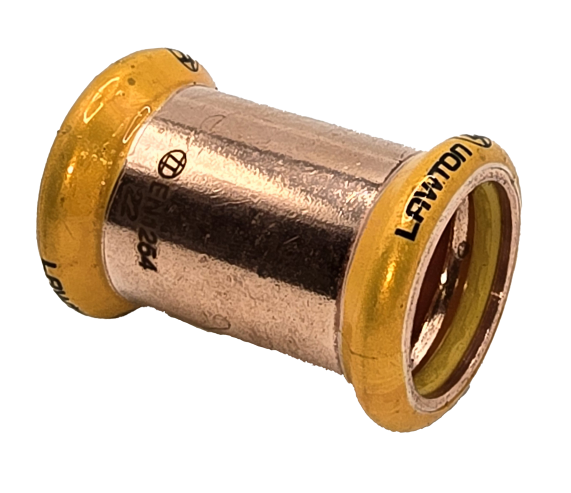
SLIP COUPLER PRESS GAS
Gas Press Fittings
| Part | Description | Size 1 | Bag | Box |
|---|---|---|---|---|
| PFGSC015 | 15MM SLIP COUPLER PRESS GAS | 15MM | 10 | 350 |
| PFGSC022 | 22MM SLIP COUPLER PRESS GAS | 22MM | 10 | 150 |
| PFGSC028 | 28MM SLIP COUPLER PRESS GAS | 28MM | 5 | 100 |
| PFGSC035 | 35MM SLIP COUPLER PRESS GAS | 35MM | 2 | 60 |
| PFGSC042 | 42MM SLIP COUPLER PRESS GAS | 42MM | 2 | 40 |
| PFGSC054 | 54MM SLIP COUPLER PRESS GAS | 54MM | 2 | 26 |
Press Gas Slip Coupler
The Lawton Press Gas Slip Coupler is designed to simplify repairs, maintenance and alterations to existing copper gas pipework systems. Its sliding design allows for easier installation where fixed pipework makes standard couplers difficult to fit.
The advanced press-fit design enables a fast, heat-free installation without the need for soldering, welding or hot works. This helps reduce downtime, minimise labour requirements and provides a secure and leak-tight connection.
Designed for use with compatible press tools, the fitting features a yellow sealing ring and Lawton’s yellow identification marking to help clearly identify its suitability for gas applications. Backed by Lawton’s industry-leading 75-Year Warranty, it provides dependable long-term performance.
Key Features
- Ideal for repairs, maintenance and pipe alterations
- Fast and efficient press-fit installation
- No soldering, welding or hot works required
- Secure, leak-tight connection
- Yellow HNBR sealing ring for gas applications
- Lawton’s yellow marking for easy identification
- Suitable for copper tube manufactured to EN1057
- Available in sizes from 15mm to 54mm
- Suitable for gas installation applications
- Backed by a 75-Year Warranty
Technical Data
Product Overview
Lawton Gas Press Fittings provide a safe, heat-free jointing solution for Family 2 and Family 3 fuel gas systems and compressed air applications. Available in sizes from 15mm to 54mm, the range features an M-profile press connection with a yellow HNBR seal and is manufactured in accordance with EN 1254-7.
Applications
- Family 2 Fuel Gas Systems
- Family 3 Fuel Gas Systems
- Compressed Air Systems
Market Sectors
- Domestic
- Commercial
Product Specifications
|
Property |
Specification |
|
Size Range |
15mm – 54mm |
|
Materials |
CW024A Copper and CW602N DZR Brass |
|
Seal Material |
Yellow HNBR O-Ring |
|
Press Configuration |
M-Profile |
|
Maximum Fuel Gas Pressure |
5 bar (Outdoors), 1 bar (Indoors) |
|
Maximum Negative Pressure |
>0.2 bar |
|
Maximum Compressed Air Pressure |
10 bar (5°C to 35°C) |
|
Ambient Temperature Range |
-20°C to +70°C |
|
Product Marking |
Size, LTC Logo, EN 1254 |
|
Electrical Continuity |
Yes |
|
Thread Specification (Male) |
ISO 7 / EN 10226-1 |
|
Thread Specification (Female) |
BS EN ISO 228 |
|
Standard |
EN 1254-7 |
|
Warranty |
75 Years* |
*Subject to standard Terms & Conditions. Please refer to our website for full details.
Standards & Compliance
|
Category |
Standard |
|
Gas Press Fittings |
EN 1254-7 |
|
Male Threads |
ISO 7 / EN 10226-1 |
|
Female Threads |
BS EN ISO 228 |
Operating Performance
|
Property |
Value |
|
Maximum Fuel Gas Pressure (Indoor) |
1 bar |
|
Maximum Fuel Gas Pressure (Outdoor) |
5 bar |
|
Maximum Compressed Air Pressure |
10 bar |
|
Ambient Temperature Range |
-20°C to +70°C |
|
Electrical Continuity |
Yes |
Copper Tube Compatibility
Compatible with copper tube manufactured to BS EN 1057.
Material Conditions
- R250 – Half-hard, bendable
- R290 – Hard, unbendable
|
Outside Diameter |
0.7mm Wall |
0.9mm Wall |
1.0mm Wall |
1.2mm Wall |
1.5mm Wall |
2.0mm Wall |
2.5mm Wall |
|
15mm |
R250 |
— |
R250 / R290 |
— |
— |
— |
— |
|
22mm |
— |
R250 |
— |
R250 / R290 |
— |
— |
— |
|
28mm |
— |
R250 |
— |
R250 / R290 |
— |
— |
— |
|
35mm |
— |
— |
R290 |
R250 / R290 |
R290 |
— |
— |
|
42mm |
— |
— |
R290 |
R250 / R290 |
R290 |
— |
— |
|
54mm |
— |
— |
— |
— |
R290 |
R290 |
R290 |
Recommended Minimum Fitting Clearance
To allow for tube deformation during pressing, the following minimum distances should be maintained between adjacent fittings.
|
Tube Size |
Minimum Clearance F (mm) |
|
15mm |
13 |
|
22mm |
13 |
|
28mm |
13 |
|
35mm |
13 |
|
42mm |
16 |
|
54mm |
20 |
Approved Press Tools
Lawton Gas Press Fittings are approved for use with M-profile press systems from:
- Novopress
- Geberit
- Rothenberger
- REMS
Important Installation Note
Matching press tools, adaptors, jaws and slings from the same manufacturer must always be used during installation.
Tool Compatibility
|
Manufacturer |
Model |
Diameter Range |
|
Novopress |
ACO103 |
15mm – 28mm |
|
Novopress |
ACO203 |
15mm – 54mm |
|
Novopress |
ACO203XL |
15mm – 54mm |
|
Geberit |
ACO103plus |
15mm – 35mm |
|
Geberit |
ACO203plus |
15mm – 54mm |
|
Geberit |
ACO203XLplus |
15mm – 54mm |
|
Rothenberger |
Compact TT |
15mm – 28mm |
|
Rothenberger |
Compact 3 |
15mm – 35mm |
|
Rothenberger |
Romax 4000 |
15mm – 54mm |
|
REMS |
Mini-Press |
15mm – 28mm |
|
REMS |
Akku-Press |
15mm – 28mm |
Material Compatibility
Dissimilar Metals
Installations containing mixed metals should generally be avoided, as galvanic corrosion may occur where different metals are connected directly together.
Where mixed-metal systems are unavoidable:
- Follow the Gas Safety (Installation and Use) Regulations 1998.
- Apply recognised engineering best practice.
- Consider suitable isolation measures where required.
1. PREPARATION:
• Ensure the O-ring is present & is seated correctly (not loose in the fitting).
• Cut the tube square.
2. TUBE PREPARATION:
• Check the tube ends are not damaged.
• De-burr the end of the tube.
• Ensure no sharp edges or swarf are present.
3. INSERTION AND DEPTH MARKING:
• Insert the tube into the fitting using a “twisting motion”.
• Using a permanent pen place a mark on the tube to indicate that the fitting is fully engaged.
• When all tubes are inserted double check the “depth marks” are in the correct position.
4. PRESS THE JOINT:
• Ensure the correct tool and jaws are selected.
• Place the jaw around the “bead” of the fitting.
• When correctly located press the trigger button to commence the pressing process.
• The tool will automatically stop when this is complete.
• Remove the pressed assembly from the jaw.