Installation Video
- Use QR code app on your smart phone or tablet to access >B< MaxiPro home page.

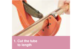
1. Cut the tube to length
- Use a rotary tube cutter.
- Ensure that the tube is cut square.
- Check the pipe has retained its shape and is damage free.
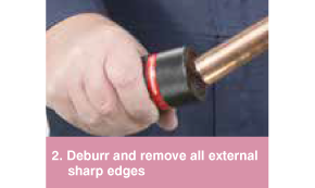
2. Deburr and remove all external sharp edges
- Deburr the tube both internally and externally.
- Where possible angle the tube downwards to prevent filings entering the tube.
- Use a pencil type deburrer on internal tube edges.
- Make sure the internal and external surfaces of the tube ends are smooth and free from burrs or sharp edges.
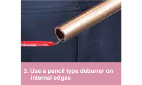
3. Use a pencil type deburrer on internal edges
- Deburr the tube both internally and externally.
- Where possible angle the tube downwards to prevent filings entering the tube.
- Use a pencil type deburrer on internal tube edges.
- Make sure the internal and external surfaces of the tube ends are smooth and free from burrs or sharp edges.
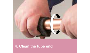
4. Clean the tube end
- Thoroughly clean the tube end using Rothenberger Rovlies or similar cleaning pad in a rotating action.
- Tube ends must be free from scratches, oxidation, dirt and debris.
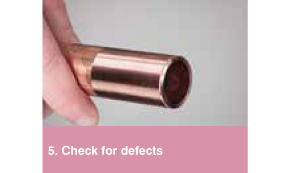
5. Check for defects
- If deep scratches are still visible, cut the tube back to a clean section.
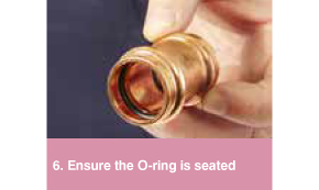
6. Ensure the O-ring is seated
- Check the fitting is the correct size for the tube.
- Check the O-rings are present and correctly seated.
- Additional >B< MaxiPro lubrication may be used to aid tube insertion.
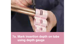
7A. Mark insertion depth on tube using depth gauge
- Insert tube into correct socket in depth gauge.
- Check window to see the tube is fully inserted.
- Mark the insertion depth on the tube.
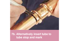
7B. Alternatively insert tube to tube stop and mark
- The tube must be fully inserted into the fitting until it reaches the tube stop.
- To reduce the risk of dislodging the O-ring rotate the tube (if possible) while slipping it into the fitting.
- Mark the insertion depth on the tube.
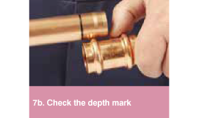
7B. Check the depth mark
- Remove the tube and align with fitting socket, check that the depth mark is correctly positioned.
- The insertion depth mark is used as a reference prior to pressing the joint.
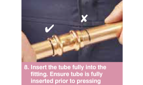
8. Insert the tube fully into the fitting. Ensure tube is fully inserted prior to pressing
- Insert the tube fully into the fitting up to the tube stop.
- To reduce the risk of dislodging the O-ring rotate the tube (if possible) while slipping it into the fitting.
- Prior to pressing ensure the tube has not moved out from the fitting socket.
- Use the insertion depth mark as a guide.
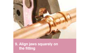
9. Align jaws squarely on the fitting
- Ensure pipework is correctly aligned prior to pressing.
- Ensure the correct size jaw is inserted into the tool.
- The jaws must be placed squarely on the fitting locating the groove on the bead.
- The bead on the fitting should fit centrally in the groove of the jaw.
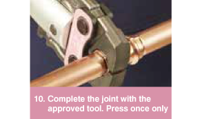
10. Complete the joint with the approved tool. Press once only
- Depress and hold the button to complete the pressing cycle.
- Pressing is complete when the jaws are fully closed and the piston retracts.
- Complete the press cycle once only – do not repress.
- Release the jaws from the pressing
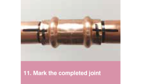
11. Mark the completed joint
- Mark the completed joint after pressing.
- This enable joints to be inspected easily before testing and insulating the pipework.