Phone
+44(0) 24 7646 6203

Our copper straight pipe diameters range from 6mm to 219mm, making them suitable for a range of projects from small domestic installations to large commercial tasks, with immediate dispatch available.
To provide you with considerable cost savings that don’t compromise on operating performance, Lawton Tubes also offers an alternative to the traditional 1.2mm thick EN1057 straight pipe. Introducing Lawton LiteX – a hard drawn, lightweight and kitemarked tube which is available in diameters of 35mm, 42mm and 54mm.*
Packaging
All our copper straight pipes and tubes are bundle tied. 15-28mm (TX) are yellow end capped in groups of 10 (UK-market only).
Marking
Straight pipes in sizes 15mm – 108mm are stamped with:
Sizes 133mm and above are stamped at either end of the pipe/tube.
All tubes 108mm and below are inkjet marked with similar data.
Instructions for use: For straight pipes 54mm and below, use tin solder.
How to Solder Copper Fittings Instructions
Instructions for use: For straight pipes 67mm and above, use brazing rod.
How to Braze Copper Fittings Instructions
With our extensive international reach, Lawton Tubes has been privileged to collaborate on numerous large-scale construction projects using our copper straight pipes, specifically in the plumbing sector. Our portfolio encompasses prestigious ventures such as the London 2012 Olympic Stadium and Village, the USA Air Force base, Camp Eggers in Afghanistan, and Zayed University in Abu Dhabi, among others.
Working Pressures / Mechanical Properties
Dimensions and Tolerances (includes chrome plated and PVC covered)
| O.D. (mm) | Wall (mm) | Temper | Max Working Pressure bar up | Thickness Tolerance | Diameter Tolerance Mean | Diameter Tolerance Including Ovality |
| 6 | 0.6 (TX) | Half Hard | 133 | ±10% | ± 0.04mm | ±0.09mm |
| 6 | 0.6 | Soft | 90 | ±10% | ± 0.04mm | Not applicable |
| 6 | 0.8 (TY) | Half Hard | 188 | ±10% | ± 0.04mm | ±0.09mm |
| 8 | 0.6 (TX) | Half Hard | 97 | ±10% | ± 0.04mm | ±0.09mm |
| 8 | 0.6 | Soft | 66 | ±10% | ± 0.04mm | Not applicable |
| 8 | 0.8 (TY) | Half Hard | 136 | ±10% | ± 0.04mm | ±0.09mm |
| 10 | 0.6 (TX) | Half Hard | 77 | ±10% | ± 0.04mm | ±0.09mm |
| 10 | 0.7 (TY) | Soft | 62 | ±10% | ± 0.04mm | Not applicable |
| 10 | 0.8 (TY) | Half Hard | 106 | ±10% | ± 0.04mm | ±0.09mm |
| 12 | 0.6 (TX) | Half Hard | 63 | ±10% | ± 0.04mm | ±0.09mm |
| 12 | 0.8 (TY) | Half Hard | 87 | ±10% | ± 0.04mm | ±0.09mm |
| 15 | 0.7 (TX) | Half Hard | 58 | ±10% | ± 0.04mm | ±0.09mm |
| 15 | 1.0 (TY) | Half Hard | 87 | ±13% | ± 0.04mm | ±0.09mm |
| 15 | 1.0 (TY) | Soft | 67 | ±13% | ± 0.04mm | Not applicable |
| 22 | 0.9 (TX) | Half Hard | 51 | ±10% | ± 0.05mm | ±0.10mm |
| 22 | 1.2 (TY) | Half Hard | 69 | ±15% | ± 0.05mm | ±0.10mm |
| 22 | 1.2 (TY) | Soft | 57 | ±15% | ± 0.05mm | Not applicable |
| 28 | 0.9 (TX) | Half Hard | 40 | ±10% | ± 0.05mm | ±0.10mm |
| 28 | 1.2 (TY) | Half Hard | 55 | ±15% | ± 0.05mm | ±0.10mm |
| 35 | 1.0 (LiteX) | Hard | 42 | ±15% | ± 0.06mm | ±0.07mm |
| 35 | 1.2 (TX) | Half Hard | 42 | ±10% | ± 0.06mm | ±0.11mm |
| 35 | 1.5 (TY) | Hard | 64 | ±10% | ± 0.06mm | ±0.07mm |
| 42 | 1.0 (LiteX) | Hard | 35 | ±15% | ± 0.06mm | ±0.07mm |
| 42 | 1.2 (TX) | Half Hard | 35 | ±10% | ± 0.06mm | ±0.11mm |
| 42 | 1.5 (TY) | Hard | 53 | ±10% | ± 0.06mm | ±0.07mm |
| 54 | 1.2 (TX) | Hard | 33 | ±15% | ± 0.06mm | ±0.07mm |
| 54 | 2.0 (TY) | Hard | 55 | ±10% | ± 0.06mm | ±0.07mm |
| 66.7 | 1.2 (TX) | Hard | 26 | ±15% | ± 0.07mm | ±0.10mm |
| 66.7 | 2.0 (TY) | Hard | 45 | ±15% | ± 0.07mm | ±0.10mm |
| 76.1 | 1.5 (TX) | Hard | 29 | ±15% | ± 0.07mm | ±0.10mm |
| 76.1 | 2.0 (TY) | Hard | 39 | ±15% | ± 0.07mm | ±0.10mm |
| 108 | 1.5 (TX) | Hard | 20 | ±15% | ± 0.07mm | ±0.20mm |
| 108 | 2.5 (TY) | Hard | 34 | ±15% | ± 0.07mm | ±0.20mm |
| 133 | 1.5 (TX) | Hard | 16 | ±15% | ± 0.20mm | ±0.70mm |
| 159 | 2.0 (TX) | Hard | 18 | ±15% | ± 0.20mm | ±0.70mm |
| 219 | 3.0 (TX) | Hard | 20 | ±15% | ± 0.60mm | ±1.50mm |
| O/D mm | Capacity kg/m |
| 6 | 0.0169 |
| 8 | 0.0347 |
| 10 | 0.0558 |
| O/D mm | Capacity kg/m |
| 6 | 0.0169 |
| 8 | 0.0347 |
| 10 | 0.0615 |
| 12 | 0.0890 |
| 15 | 0.1416 |
| 18 | 0.2063 |
| 22 | 0.3140 |
| 28 | 0.5308 |
| 35 | 0.8220 |
| 42 | 1.2163 |
| 54 | 2.0712 |
| 67 | 3.2134 |
| 76 | 4.1699 |
| 108 | 8.6107 |
| 133 | 13.2647 |
| 159 | 18.8351 |
Table Y 6mm – 108mm
| O/D mm | Capacity kg/m |
| 6 | 0.0139 |
| 8 | 0.0302 |
| 10 | 0.0529 |
| 12 | 0.0818 |
| 15 | 0.1280 |
| 18 | 0.1952 |
| 22 | 0.2943 |
| 28 | 0.5050 |
| 35 | 0.7888 |
| 42 | 1.1758 |
| 54 | 1.9317 |
| 67 | 3.2375 |
| 76 | 4.0438 |
| 108 | 8.2527 |
Copper has a coefficient of linear expansion of 17 x 10-60ºC. For example, a 10m length of copper pipe carrying hot water at 60ºC will increase in length by almost 7mm when heated from 20ºC. Assuming the temperature cycling of the system is 20ºC, there will be a continuous cycle of expansion and contraction of 3.4mm. Refer to table below.
| Temperature change | 3m | 4m | 5m | 6m | 7m | 8m | 9m | 10m | 12m | 25m |
| 10° | 0.5mm | 0.7mm | 0.9mm | 1.0mm | 1.2mm | 1.4mm | 1.5mm | 1.7mm | 2.0mm | 4.3mm |
| 20° | 1.0mm | 1.4mm | 1.7mm | 2.0mm | 2.4mm | 2.7mm | 3.0mm | 3.4mm | 4.0mm | 8.5mm |
| 30° | 1.5mm | 2.0mm | 2.6mm | 3.1mm | 3.6mm | 4.1mm | 4.6mm | 5.1mm | 6.1mm | 13.0mm |
| 40° | 2.0mm | 2.7mm | 3.4mm | 4.1mm | 4.8mm | 5.4mm | 6.1mm | 6.8mm | 8.2mm | 17.0mm |
| 50° | 2.6mm | 3.4mm | 4.3mm | 5.1mm | 6.0mm | 6.8mm | 7.7mm | 8.5mm | 10.2mm | 21.0mm |
| 60° | 3.1mm | 4.1mm | 5.1mm | 6.1mm | 7.1mm | 8.2mm | 9.2mm | 10.2mm | 12.2mm | 26.0mm |
| 70° | 3.6mm | 4.8mm | 6.0mm | 7.1mm | 8.3mm | 9.5mm | 10.7mm | 11.9mm | 14.3mm | 30.0mm |
| 80° | 4.1mm | 5.4mm | 6.8mm | 8.2mm | 9.5mm | 10.9mm | 12.2mm | 13.6mm | 16.3mm | 34.0mm |
| 90° | 4.6mm | 6.1mm | 7.7mm | 9.2mm | 10.7mm | 12.2mm | 13.8mm | 15.3mm | 18.4mm | 38.0mm |
| 100° | 5.1mm | 6.8mm | 8.5mm | 10.2mm | 11.9mm | 13.6mm | 15.3mm | 17.0mm | 20.4mm | 43.0mm |
| 150° | 7.65mm | 10.2mm | 12.75mm | 15.3mm | 17.85mm | 20.4mm | 22.95mm | 25.5mm | 30.6mm | 63.75mm |
| 200° | 10.2mm | 13.6mm | 17.0mm | 20.4mm | 23.8mm | 27.2mm | 30.6mm | 34.0mm | 40.8mm | 85.0mm |
Copper straight pipe installations have been tried and tested over many years of use in all parts of plumbing and heating systems. Copper’s versatility in such a wide variety of situations has resulted in the design and development of many different types of fixing clips and bracketing systems.
All pipework systems must be adequately supported if they are to give trouble-free service, especially over the long life of a copper system, some of which is illustrated in Figure 1.
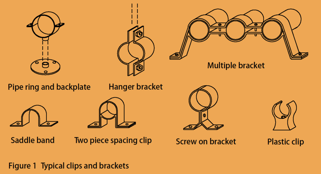
Choosing the most appropriate clip or bracket depends on several factors that vary with the type of job and position or situation in which the straight length is installed.
For example, the pipe must be insulated against heat or frost in accordance with water regulations. In this situation, a simple plastic stand-off clip will not give sufficient clearance for the thickness of insulation required between the tube and the fixing surface. Therefore, an alternative type of support must be chosen, such as a ring bracket with a threaded rod and backplate.
Another factor which can affect an installation is the actual number of tube supports required. Because copper tube is a relatively rigid and self-supporting material, it requires comparatively fewer supports when compared to non-metallic tube.
You will find the recommended intervals set out in Table 1 (below), which shows that fewer supports are required for vertical runs. This is because vertical straight lengths will not be subjected to possible sagging between supports. Excessive sagging can occur on horizontal runs of pipes made from any material if the supports are too far apart.
Another factor which must be considered, especially when considering supports for larger diameter tube and/or lightweight building structures is the method to be used to fix the tube support to the building fabric. The fixing method used should be able to transmit the weight of the tube and its contents to the building fabric, as well as any withstanding any other forces acting on the tube, without damage.
| Diameter of Copper Pipe (mm) | Intervals for Vertical Runs (m) | Intervals for Horizontal Runs (m) |
| 6 | 0.6 | 0.4 |
| 8 | 0.9 | 0.6 |
| 10 | 1.2 | 0.8 |
| 12 | 1.5 | 1 |
| 15 | 1.8 | 1.2 |
| 22 | 2.4 | 1.8 |
| 2.4 | 2.4 | |
| 28 | 3 | 2.4 |
| 35 | 3 | 2.7 |
| 42 | 3 | 3 |
| 54 | 3 | 3 |
| 67 | 3.6 | 3 |
| 76 | 3.6 | 3 |
| 108 | 3.6 | 3 |
| 133 | 3.6 | 3 |
| 159 | 4.2 | 3.6 |
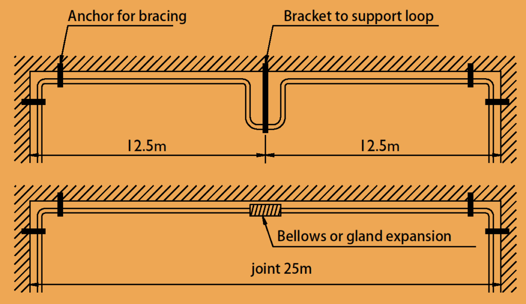
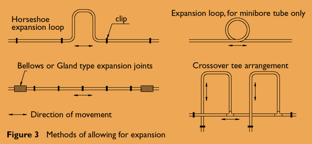
For long copper straight pipe runs using hanging brackets, anchor bracing should be installed at 12m centers to prevent swaying of the straight pipe. In hot water lines, the allowable copper pipe length between anchor fixings and expansion joints depends on the joint’s type and movement capacity. Anchoring copper length at changes in direction (Figure 2) allows expansion to be managed by joints or expansion loops (installed horizontally to avoid airlocks).
For gland-type joints experiencing a 60°C temperature change and accommodating 25mm of expansion, the copper pipe length each side of the joint to an anchor can be up to 12.5m. This is because each meter of copper straight pipe changes in copper length by approximately 1mm per 60°C. Bellows-type joints should be installed with a “cold draw” to allow for expansion of the straight pipe.
Branch joints can serve as anchors, but “cross-over tees” (Figure 3) are needed if the connected copper pipe length will also move due to thermal expansion. Proper alignment of all straight pipe runs is crucial to prevent strain, especially when connecting copper pipe length to plastic cisterns, where backing plates or washers should be used to distribute load.
All tube runs should be aligned correctly to prevent undue strain. This is particularly important when connecting tube to a plastic cistern. Suitable backing plates or washers without sharp edges should be fitted between the tube connection and the cistern to spread any load.
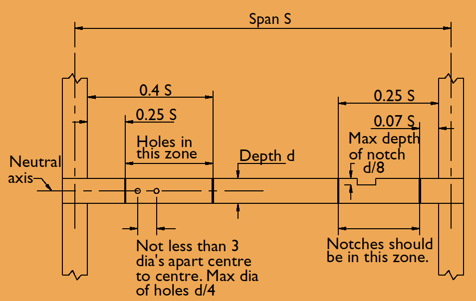
Notches and holes in simply supported floor and roof joists should be within the following limits:
Drilled holes should be no greater in diameter than 1/4 of the depth of the joist. They should be drilled on the neutral axis and should be not less than 3 diameters apart, measured from centre to centre. Holes should be located in the area between 0.25 and 0.4 times the span of the joist from the support.
Note: Notches or holes for pipes must NOT be cut in roof rafters. Figure 4 shows the permitted limits of notches and holes in floor and roof joists.
The ability to drill holes through joists means that where soft coiled copper tube
(up to 10mm O.D. Table W or up to 12mm O.D. Table Y) is to be installed, it is quite easy to drill and cable the tube through the joists. This means that in new build work the tube can sometimes, if desired, be installed from below after the floorboards have been laid but before ceilings are boarded.
Where straight lengths of half–hard copper tube are required to be run in floors, they can be laid in notches. By using pipe joist clips with integral protective metal plates, the risk of damage due to punctures from nailing accidents should be eliminated. The rectangular shape of the joist clip can be used as a template when notching joists, which should avoid the joists being weakened accidentally by excessively deep notches.
Although unseen when the installation is complete, joist clips improve the overall quality of the installation. They do this by helping to align the straight length and permit expansion movement due to temperature changes in hot water lines. This will help to prevent clicking noises and the water hammer which can arise due to badly aligned pipework.
All our copper pipes are manufactured to BS EN1057, ISO 9001, and are kitemarked.
Our minimum order for copper straight pipes is 1,000kgs of copper tube for FOC (approx. £6,000 ex VAT in value). For larger orders, please get in touch and we’ll be happy to help.
A large proportion of copper for our products, including our copper straight pipes and tubes, is mined in Chile. There are around 30 processing plants and factories around the world with a variety of capabilities, and, at Lawton Tubes, we have two drawing plants based in the UK.
Copper Pipe Straight Length

